





An insulation piercing connector (IPC) is a clamp-type fitting that connects an insulated cable without stripping it. Tightening the bolt drives hardened contact teeth through the insulation and into the conductor; the body and seals then close the puncture, so the joint stays both electrically sound and insulated.
On distribution networks, IPCs are the standard branch and service fitting for low-voltage overhead lines — most often on aerial bundled cable (ABC) rated 0.6/1 kV. This article explains how the connection is made, what each part does, where the fitting belongs, and how to specify one. For deeper engineering detail, see our comprehensive guide to insulation piercing connectors.
Four things have to happen in one tightening action: the teeth cut through the insulation, bite into the metal, hold contact force as the joint heats and cools, and the puncture is resealed. An IPC is designed as a system of parts for that reason — a sharpened plate on its own would satisfy only the second of the four.
The contact plates carry several hardened teeth per conductor groove. As the body closes, the teeth cut a clean slot in the XLPE or PVC insulation and press into the conductor. Two things follow: the teeth displace the aluminium oxide film that re-forms immediately on exposed aluminium and would otherwise sit between the metals, and they press the conductor against the contact plate at a defined force, so the joint depends on a controlled contact area rather than on incidental touch.
Contact force is held by the elasticity of the body working against bolt tension, which is why torque decides whether the joint stays stable. An under-tightened joint carries too little force; an over-tightened one can relax the body or damage strands. Neither shows up immediately — both tend to show up later as heat.
LV connectors are tightened until the nut's shear head snaps off. The head is machined to break at a defined torque, so the installer works to the connector's own setting instead of judgement, and no torque wrench is needed at the top of a pole. A sheared head also serves as a visible completion check. Two-bolt models such as the two-bolt ZOP-257 apply the same principle across two bolts, spreading clamp force over a longer length of conductor.
Every tooth that pierces insulation leaves a hole. The body closes around both conductors, an elastomer element sits between the body halves, and the end cap closes the branch entry. Correctly sized and fully closed, this keeps water out of the contact zone — and moisture reaching a current-carrying contact is one of the mechanisms that degrade an overhead joint over time, which is why the seal is a functional part and not a cosmetic one.
The seal has limits: it depends on the cable's outside diameter falling inside the connector's range, on the body being fully closed, and on the end cap being fitted. Where the network design calls for an enclosure or a specific ingress rating, use that accessory rather than relying on the connector's own seal.
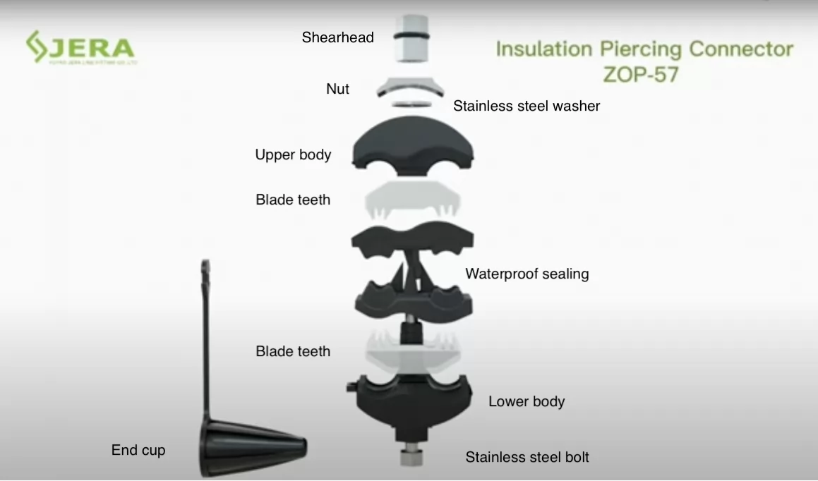
An LV insulation piercing connector is an assembly of eight to ten parts. The exploded view above is a JERA LINE ZOP-57; the function of each group is the same across the range, though materials vary by model.
| Part | What it does | Typical material |
|---|---|---|
| Shear-head nut | Tightens the joint and breaks off at the specified torque | Aluminium alloy |
| Bolt | Carries clamp load through the body | Stainless steel |
| Washer | Spreads load beneath the nut, resists galling | Stainless or coated steel |
| Upper and lower body | Insulates, positions both conductors, carries clamp load | UV- and heat-resistant polymer, usually a two-component insert moulding with elastomer |
| Blade teeth (contact plates) | Pierce insulation and establish electrical contact | Tin-coated aluminium, or tin-coated brass on smaller models |
| Waterproof sealing element | Closes the puncture around both conductors | Elastomer |
| End cap | Seals the branch cable entry | Elastomer, rubber or PP, depending on model |
Materials differ between models, so the component table on each product page is authoritative for that model.
The body has to insulate, hold two cables at a fixed distance under sustained load, survive UV and thermal cycling, and still be mouldable around metal inserts. Polyamide — PA6, PA66 and glass-fibre-reinforced variants — is widely used in this class because it combines mechanical strength with good creep behaviour and moulding precision.
The material name alone tells you little: unstabilised PA6 absorbs moisture and degrades under UV, while a well-formulated housing uses stabilisers, often glass-fibre reinforcement, and is validated by climatic-ageing and UV tests. So when a specification says “polyamide”, ask which grade, what reinforcement and which ageing tests it passed. JERA's pages specify a heat- and UV-resistant two-component insert moulding of composite polymer and elastomer; if your utility names PA6 explicitly, get the grade in writing.
The products described here are low-voltage overhead distribution fittings rated up to 1 kV. That scope decides which networks they belong on and, just as importantly, which they do not.
ABC is the main application: a branch tap on a four-core main, a service tee at a pole, a lighting circuit taken off the same bundle. Because the main conductor is neither cut nor re-jointed, the fitting can be added to an existing run, and the joint arrives factory-sealed rather than being taped at height. For one-core and four-core constructions, see insulation piercing connectors for one-core LV ABC.
Service work is where size range matters most: the main may be 95 or 150 mm² while the service cable is 16 mm². Small-size models exist for exactly this — the ZOP-45P takes a 4–70 mm² main and a 1.5–16 mm² tap with a tin-coated brass contact plate, and JERA describes it for street-lighting circuits and solar plant strings. Where several services leave one point, multi-tap insulation piercing connectors take two branch conductors in a single fitting.
Dedicated variants cover the adjacent jobs: tapping a surge arrester lead from an ABC main, and transitioning between bare and insulated conductor. These are separate designs, not adaptations of a branch connector.
All four depend on correct selection and installation — the mechanism only delivers them if the joint is specified and fitted as a system.
Four checks decide most specifications: both conductor ranges, the metal combination, the voltage class, and the standard to quote.
Every IPC has two independent ranges — main and tap (branch), both in mm². Both conductors must fall inside their respective ranges; a connector that fits the main says nothing about the tap.
| Model | Main, mm² | Tap, mm² | Contact plate | Metals stated by JERA | Typical use |
|---|---|---|---|---|---|
| ZOP-2 | 16–95 | 4–35 | Tin-coated aluminium | Al and Cu | General LV ABC branch connections |
| ZOP-54 | 16–150 | 4–50 | Tin-coated aluminium | Al and Cu | Larger LV ABC mains |
| ZOP-56 | 25–185 | 6–35 | Tin-coated aluminium | Al and Cu | LV ABC up to 1 kV |
| ZOP-57 | 25–185 | 25–95 | Tin-coated aluminium | Al and Cu | Large tap conductors |
| ZOP-45P | 4–70 | 1.5–16 | Tin-coated brass | Al and Cu (implied only) | Street lighting, solar plant strings |
| ZOP-257 | 25–150 | 25–95 | Tin-coated aluminium | Al and Cu | Two-bolt clamping for large service taps |
| MTT-235 | Not published — confirm on datasheet | 2 × 4–35 | Tin-coated aluminium | Not stated on page | Two branch services from one point |
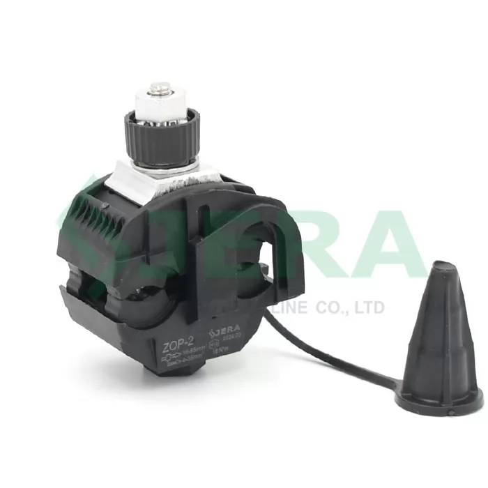
Outside diameter matters as much as cross-section, because sealing depends on the body closing around the actual sheath — jacketed ABC and ABC with a bare neutral differ at the same mm². For critical joints, prefer the model where your size sits comfortably inside the range rather than at its limit. Ranges are as published on each product page; confirm against the current datasheet before ordering.
The published range and the tested range are two different numbers. ZOP-57 illustrates the gap: the product page publishes a 25–185 mm² main, while JERA's own NF C 33 020 type-test announcement cites the tested article as ZOP-57 (25–150 / 25–95). Neither figure is necessarily wrong — a test programme is run on the sizes the laboratory was given, and a design can be offered beyond them — but a report for 25–150 does not evidence 185. If your main conductor sits between 150 and 185 mm², ask for the report that covers the size you are actually buying, and take the latest issued document over any web page.
Joining aluminium to copper in a damp, current-carrying joint creates a galvanic couple, and the usual mitigation in this product class is a plated contact surface between the dissimilar metals. In the ZOP range most models are published with tin-coated aluminium teeth and described as suitable for both aluminium and copper conductors; the ZOP-45P uses a tin-coated brass contact plate instead.
Contact material and approved application are two different things. A plated contact surface is a necessary part of a bimetallic design, but it does not by itself establish that a given connector is approved for your metal combination — that is a property of the individual model, stated on its own product page and covered, or not, by its own test report. Read the model, not the material. Copper is also harder than aluminium, so confirm that a connector is rated for copper conductor rather than merely containing copper alloy somewhere in its construction.
LV connectors are rated up to 1 kV and belong on LV ABC, service and lighting circuits. MV IPC connectors are a separate class up to 36 kV with different insulation and test requirements. Within LV, check whether the ABC carries an insulated or a bare neutral messenger, because that changes the model.
Bodies are UV-stabilised for permanent outdoor exposure, hardware is stainless or coated steel, seals are elastomer. Coastal and industrial atmospheres put the emphasis on salt-spray performance; hot climates on UV and thermal ageing. Ask which ageing tests the model has passed rather than assuming the polymer description covers it.
Quote the standard your utility actually specifies — for LV ABC branch connectors the usual references are NF C 33-020 and the EN 50483 series, and JERA's product pages cite EN 50483-4 — then ask for the type-test report that names your model and size range. A certificate of compliance is not the same document as a report.
The sequence below is common to most LV shear-head models. The instructions for the specific model, the utility's working procedure and local safety rules take precedence in every case.
A holding tool such as the JTN-7-13 for LV models keeps the connector square while torque is applied, which matters on a pole in wind. Our LV overhead IPC installation guide covers the sequence step by step; the video below shows it on a real joint.
Two different things are tested, and buyers often conflate them. Type tests validate a design once, at an independent laboratory, and the scope is listed in the report itself.
The scope JERA publishes for the ZOP-2 EN 50483-4 report, for example, reads: visual examination; dimensional and material verification; test for permanent marking; test for mechanical damage to the main conductor; branch cable pull-out; connector bolt tightening; shear-head function; low-temperature impact; dielectric voltage test in water; low-temperature assembly; corrosion ageing; climatic ageing; electrical ageing. Treat that as an indicative list rather than a clause-by-clause reading of the standard — the authoritative scope is whatever the report for your model states, and a report covers only the sizes that were tested.
Routine tests are production checks — visual examination, permanent marking, dielectric test in water, shear-head function — carried out in JERA's factory laboratory. How often they are applied (every unit, or a sample per batch) is set in the manufacturer's quality plan rather than in the standard, so ask which routine test record the factory can supply for the batch you receive instead of assuming a frequency.
On the standard itself: NF C 33-020 defines the characteristics and tests applicable to insulation piercing branch connectors for overhead distribution and service with bundled assembled cores rated 0.6/1 kV. It is not a general “low-voltage installation” standard, and it is not a product certification. The tightening torque is whatever the connector's own instruction sheet specifies.
JERA publishes model-specific third-party reports rather than a single family claim — for example the NF C 33 020 type test for the ZOP-57 and the ZOP-54 NF C 33 020 report, alongside EN 50483-4 reports for individual models. Coverage is not uniform across the table above. The ZOP-57 case shows why the size range has to be read with the report rather than off the product page: that NF C 33 020 announcement cites the tested article as 25–150 / 25–95 mm², while the product page publishes 25–185 / 25–95. Ask for the report that names your model and covers your size, and ask which issue of it is current.
JERA LINE manufactures LV and MV overhead connection products at its Yuyao, Ningbo factory, with insulation piercing connectors in production since 2015. The LV range covers the applications above:
See the full overhead cable piercing connector range up to 1 kV, or browse the wider connector and clamp catalogue.
Insulation piercing connector. The same fitting is sold as a piercing connector, insulation tap connector or IPC clamp. “IPC” means several unrelated things in other industries, so spell it out in a procurement document.
Yes, if that specific model is stated by the manufacturer as suitable for both metals — most ZOP models are, using tin-coated aluminium teeth, while the ZOP-45P uses a tin-coated brass plate. Confirm the metal combination against the model's own page or datasheet rather than the family description, and state it in the enquiry.
No. Each connector has a main range and a separate tap range, and both conductors must fall inside them — the ZOP-2, for example, takes 16–95 mm² on the main and 4–35 mm² on the tap. See the selection table above for the range of each model.
Confirm four things: main conductor size and material, tap size and material, whether the ABC has an insulated or bare neutral, and the standard your utility specifies. Then pick the model whose ranges contain both conductors with some margin.
NF C 33-020 and the EN 50483 series for LV ABC branch connectors, plus your own utility specification. Ask for the third-party type-test report naming the exact model and size range, and for the routine test record covering the batch.
Matching a connector takes four lines of information. Send us:
With those four lines we can confirm the model and size range and quote. Tell us as well which documents your project requires — datasheet, type-test report or declaration — and we will confirm what is available for that specific model.
Prefer to write it out? Send your cable specification to our team and we will come back with the model, the available documentation and the price. You can also download the LV/MV cable connectors catalogue (PDF, 13.6 MB).